Street light circuit.
Electronic projects for students :- Pro1

Notes.
9v power supply circuit

Street light circuit.
Description.
The circuit diagram
present here is that of a street light that automatically switches ON
when the night falls and turns OFF when the sun rises. In fact you can
this circuit for implementing any type of automatic night light.
The circuit uses a Light Dependent Resistor (LDR)
to sense the light .When there is light the resistance of LDR will be
low. So the voltage drop across POT R2 will be high.This keeps the
transistor Q1 ON. The collector of Q1(BC107) is coupled to base of
Q2(SL100). So Q2 will be OFF and so do the relay. The bulb will remain
OFF.
When night falls the resistance of LDR
increases to make the voltage across the POT R2 to decrease below 0.6V.
This makes transistor Q1 OFF which in turn makes Q2 ON. The relay will
be energized and the bulb will glow.
Circuit diagram with Parts list. 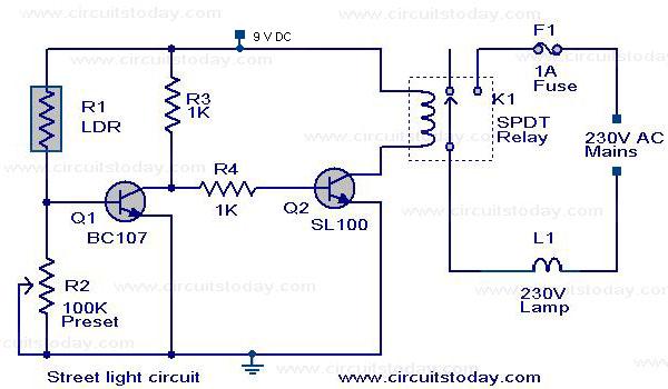
Notes.
- POT R2 can be used to adjust the sensitivity of the circuit.
- You can use bulb of any wattage, provided that relay should have the sufficient rating.
- The circuit can be powered from a regulated 9V DC power supply.
- The relay K1 can be a 9V SPDT relay.
9v power supply circuit
Here is the circuit
diagram of 9 V regulator using popular 7809 IC. The 7809 is a 9 Volt
voltage regulator IC with features such as internal current limit, safe
area protection, thermal protection etc. A 16 V transformer brings down
the 230V mains, 1A bridge rectifier rectifies it and capacitor C1
filters it and 7809 regulates it to produce a steady9V DC output.
Circuit diagram with Parts list.

Notes.
- If a current of 300 mA or above is required, fit a proper heat sink to the IC 7809.
- If 1A bridge is not available, make one using four 1N 4007 diodes.


Comments
Post a Comment